
Google has not performed a legal analysis and makes no representation or warranty as to the accuracy of the list.) ( en Inventor Clifford Rix Mark Timothy Gilbert Current Assignee (The listed assignees may be inaccurate. Google has not performed a legal analysis and makes no representation as to the accuracy of the status listed.) Expired - Fee Related Application number CA002113724A Other languages French ( fr)
#TRIHEDRAL REFLECTOR PDF#
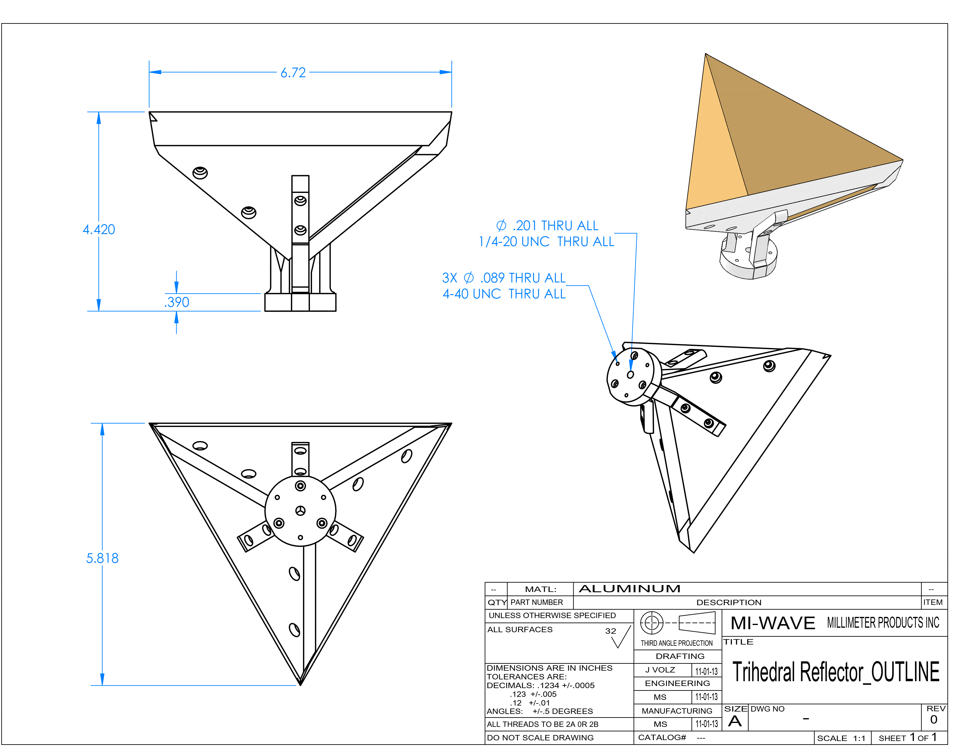
In this part of the tutorial lesson, open the property dialog of the plane wave source and change its Polarization to TEz.- Google Patents CA2113724C - Radar reflectorsĭownload PDF Info Publication number CA2113724C CA2113724C CA002113724A CA2113724A CA2113724C CA 2113724 C CA2113724 C CA 2113724C CA 002113724 A CA002113724 A CA 002113724A CA 2113724 A CA2113724 A CA 2113724A CA 2113724 C CA2113724 C CA 2113724C Authority CA Canada Prior art keywords radar lens reflector reflectors dielectric constant Prior art date Legal status (The legal status is an assumption and is not a legal conclusion. So far, you have used a TM-polarized plane wave source to illuminate your target. Contrast this with the total physical surface area of the trihedral reflector, which is merely 0.25m 2 or -6dBm 2. As you can see from the above RCS plot, the result predicted by EM.Illumina's iterative Physical Optics (IPO) solver is very close to the analytical value. Where a = 500mm is the side dimension of each plate. There is an analytical solution for the RCS of a trihedral corner reflector, which gives the maximum value of the RCS as: The dB-scale 2D Cartesian graph of the RCS of the trihedral corner reflector in the custom φ = 45° plnae.

Then, enter the coordinates, dimensions along the three principal axes and the number of sample along those axes for each field sensor observable. For example, the Z-direction places a horizontal sensor plane parallel to the principal XY plane. In the sensor dialog, first set the orientation of the field sensor plane using the Direction drop-down list. Right-click on the Near-Field Sensors item under the "Observables" section of the navigation tree and select Insert New Observable. For this project, you need to define three orthogonal near-field sensor observables according to the table below. Set the values of both the theta and phi angle increments equal to 1°. Keep in mind that you kept the default Polarization type TMz.įor the simulation observables of your project, define a current distribution observable called "CD_1" and a radar cross section observable called "RCS_1" just like in Tutorial Lesson 1. Note the location and orientation of the plane wave trident at the corner of this box. The magenta plane wave box appears around your physical structure. Setting the incidence angles in the plane wave dialog.


 0 kommentar(er)
